1, use and function
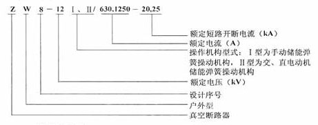
ZW8-12/630 (1250) -20,25 "type of outdoor high voltage vacuum circuit breaker, Department of three-phase AC 50Hz outdoor high-voltage equipment. Has he, load current, overload current, closing, opening off the short circuit current, its itself also has 1 switching functions, with isolation switch interlocking function, because of its life and not long maintenance cycle (10 15 years), is particularly suitable for places with frequent operation, not yet to site operation, but also can realize the remote control.
2, models and implications
3, the working conditions are as follows:
3.1 the temperature of the air around the upper limit of +40 ℃, -30 ℃.
3.2 altitude: not more than 1000m.
3.3 the wind pressure does not exceed 700Pa (equivalent to the wind speed of 34m / s)
The 3.4 air pollution level III.
3.5 the maximum daily temperature does not exceed 25 ℃.
3.6 no regular violent vibration of the place.
Two, the structure, working principle and characteristics
1, the circuit breaker body
The basic structure of the 1.1 circuit breaker by the circuit breaker body and an operating mechanism (see Figure 1, figure 3, figure 4), the circuit breaker body by a conductive loop, seal, a shell body, the whole three-phase common box type structure. The conductive loop outlet silicone rubber casing, conductive support, soft connection, conductive clamp and the vacuum interrupter connected, external insulation by high-pressure casing production guarantee, the exposed surface stick on anti-aging, anti contamination of silicon rubber umbrella skirt, insulation, insulation cover by air to achieve the lower shell body is provided with. Moisture absorber (dryer).
The 1.2 circuit breaker mountain spring operating mechanism operating (see Figure 1, figure 4, figure 1) of the actuator 9 is installed on the diagram of the breaker three-phase spindle 3 of 2 above, the actuator or the opening spring 5 to drive the breaker three-phase spindle 2 rotation, pulling the insulating rod 6 and a crank arm 7, the vacuum arc extinguishing chamber 10 of the dynamic contact is closed or opened, so that the circuit breaker is on or off state.
The 1.3 circuit breaker according to user needs, can be equipped with isolation switch with manual operation, can be equipped with a lightning protection device (see Figure 4).
2, spring operating mechanism (see Fig. 5a, FIG. 5b)
2.1 the circuit breaker can be manual operating mechanism or electric actuator are configured, the actuator are spring operated type, set in the circuit breaker three-phase spindle head. The manual mechanism only manual energy storage switching, manual switch, surge absorption device and overcurrent protection function, the electric actuator requires a separate power supply, in addition to a motor energy storage, electric switch, also have manual energy storage, manual switching function, the whole structure composed of a closing spring energy storage system, too current release, surge absorber, switch tripping device, manual switching system, auxiliary switch and storage instructions and other components.
Working principle of 2.2 electric actuator
A. storage process, as shown in Figure 5A
Figure 5A mechanism in the closing without energy storage state, when the energy storage motor 14 after the power is switched on, the motor drives the eccentric wheel to rotate, hung in the storage closing spring shaft 22 is elongated, institutions began to energy storage. When the closing spring 22 is pulled to the limit pull, cut off electrical power, and energy storage the pawl is lifted, the energy storage shaft 9 by a locating member 15 hold, at this point, the energy storage action ended.
B. closing process, as shown in Figure 5A
Agencies received signal after closing, closing release 16 action, lift the holding, closing spring release energy, drive circuit breaker three-phase spindle 6 clockwise, the breaker.
Pull the tab 18 manual switching system, also can realize closing.
Mechanism of closing, the closing spring and an energy storage, in place by the positioning piece hold, and locating piece by interlocking device 19 button, the mechanism can not release energy, avoid mechanism by.
In the closing has energy storage state, institution with "0.3S - score" once reclosing operation.
C. opening process, as shown in figure 5a,
After the circuit breaker closing, once the tripping electromagnet received signal, the moving core pull, push rod breaking off machine in 20, make the trip shaft 24 to rotate and drive the half shaft 26 to the counter clockwise rotation, the rocker arm 30 trip, circuit breakers.
Pull the tab 21 manual switching system, can realize the opening.
When current flows through the release coil value exceeds 5A, overcurrent release action, so that the rocker arm trip, circuit breaker.
Working principle of 2.3 manual organ, as shown in Figure 5B.
The mechanism of internal and motor structure is basically the same, but the closing spring without holding structure, a midpoint is closing, except no axis auxiliary switch, travel switch, a positioning body, energy storage motor, closing release, the brake release, and other motor structure, there is no longer a tag.
3, over current protection system
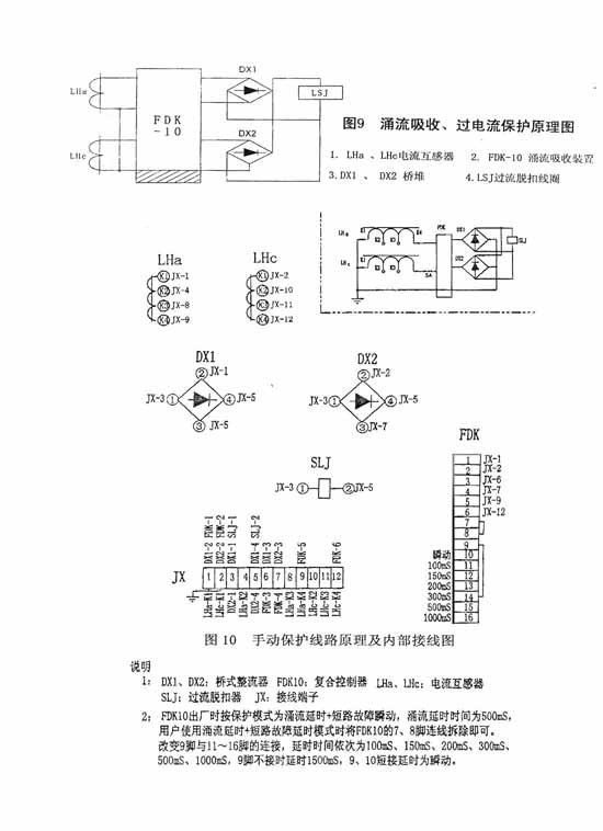
3.1 overcurrent protection system is composed of a current transformer, inrush current absorption device and overcurrent release (see Figure 9), protective function it has overload and short-circuit current to the circuit breaker of the inrush current, while absorbing the circuit breaker in the closing moments, but not the power of misclassification thyristor release.
A. two string type, three level of precision current transformer for protection, there are three ratio (200 / 5, 400 / 5, 600 / 5) of the tap, inner sheathed on the circuit breaker box cover the lower part of the high voltage silicon rubber tube (see Figure 3), the ratio value of the current transformer is according to user needs to be wound, the number also can increase or decrease according to user requirements.
B. over current tripping device is installed within the operating mechanism, the two electrical overcurrent tripping coil in series in the current transformer, a current flowing through the trip coil current of more than 5A, the overcurrent trip the circuit breaker action. It has the protective function overload and short circuit current to the circuit breaker. The technical parameters are shown in Table 4
C. surge absorbing device is an overcurrent tripping coil mounted on the protection circuit of current mutual enough for two circuit, its function is the instantaneous strong current circuit breaker in the closing moments due to the actual existence of impedance of 10KV distribution lines (caused by inrush current) in the two side short-circuit current transformer, do not make the inrush current into the overcurrent release coil to generate wrong tripping action. Surge absorption device mounted on the circuit breaker switch., the electrical principle diagram shown in figure 9.
4, with the isolation knife brake band (see Figure 4)
4.1 the circuit breaker can be equipped with manual diaphragm switch. The switch of three-phase spindle is equipped with a switch in the spring, can be accelerated at the end of the switching action, make the isolation knife brake flexible action is powerful. The upper isolation switch blade covered with a silicon rubber protective cover, can to prevent pollution and icing, to ensure the reliability of closing movement. In order to ensure the isolation switch can only be based on no load current action, equipped with a mechanical interlock structure between the isolating switch and circuit breaker body. This structure ensures that the isolation switch only closing state in the circuit breaker can be divided into action, when the circuit breaker closing to the three-phase spindle isolation switch from top dead, isolation switch to action.
4.2 loading manual isolation switch, can only use the operating rod pull the switch lever 7 (see Figure 4) for manual switching operation. The manual operation of the order: A. switch, the first switch a closed vacuum circuit breaker: B, tripping, divide and vacuum circuit breaker after the isolation switch. Operation must strictly follow this order.
4.3 isolation switch can have the lightning protection function (see Figure 4). The support insulator isolation switch static contact, according to the needs of the user can be gapless Zinc Oxide arrester is a 10KV voltage level; it is a can withstand the strong impact of the blade support insulator. The technical parameters are shown in Table 7
Three, the main technical parameters
1, the circuit breaker main technical parameters are shown in Table 1
|
Serial number
|
Project
|
Company
|
Numerical
|
|
|
1
|
Rated voltage
|
KV
|
12
|
|
|
2
|
Rated current
|
A
|
6301250
|
|
|
3
|
Power frequency withstand voltage (1min)
|
KV
|
42
|
|
|
4
|
Rated lightning impulse withstand voltage (peak)
|
KA
|
75
|
|
|
5
|
Rated short-circuit breaking current
|
20
|
25
|
|
|
6
|
Rated short-circuit current
|
50
|
63
|
|
|
7
|
Rated peak withstand current
|
50
|
63
|
|
|
8
|
Rated short-time withstand current of 4S
|
20
|
25
|
|
|
9
|
Rated operating sequence
|
|
-0.3S-, -180S- score
|
|
|
10
|
Rated short-circuit breaking current times
|
Time
|
30
|
|
|
11
|
The life of the machine
|
10000
|
||
|
12
|
The energy storage motor rated voltage
|
V
|
-24 -48 -110 -220
|
|
|
13
|
Rated operational voltage
|
-24 -48 -110 -220
|
||
|
14
|
A rated current tripping device
|
A
|
5
|
|
|
15
|
Dynamic and static contact allowed to wear thickness
|
Mm
|
3
|
|
|
16
|
Weight
|
Kg
|
133 (Ⅰ)
|
143 (II)
|
|
Serial number
|
Project
|
Company
|
Numerical
|
|
1
|
Contact distance
|
Mm
|
10~12
|
|
2
|
Contact overtravel
|
3~4
|
|
|
3
|
Average opening velocity
|
M/s
|
0.9~1.5
|
|
4
|
Average closing speed
|
0.4~0.8
|
|
|
5
|
Bounce time
|
Ms
|
2
|
|
6
|
Three-phase tripping over the same period of time
|
2
|
|
|
7
|
Closing time (with electric spring operation mechanism)
|
S
|
0.04~0.06
|
|
8
|
Opening time (with electric spring operation mechanism)
|
0.03~0.05
|
|
|
9
|
Each phase DC resistance of circuit
|
Micro ohm
|
200
|
|
10
|
Interphase center distance
|
Mm
|
175
|
|
11
|
The closing state contact spring length
|
30
|
|
Rated working voltage of Ue (V)
|
-24
|
-48
|
-110
|
-220
|
-110
|
-220
|
|
|
|
The closing coil
|
10
|
6
|
2.6
|
1.11
|
2.3
|
1.1
|
|
Closing coil
|
5.3
|
2.2
|
0.99
|
0.51
|
1.23
|
0.5
|
|
|
20 ℃ coil resistance (Ω)
|
The closing coil
|
2.4
|
8
|
42
|
198
|
10.7
|
42
|
|
Closing coil
|
4.5
|
22
|
111
|
430
|
13.7
|
54
|
|
|
Rated power (W)
|
The closing coil
|
240
|
288
|
288
|
240
|
253
|
242
|
|
Closing coil
|
130
|
106
|
109
|
112
|
135
|
110
|
|
|
The normal working voltage range
|
The closing coil
|
AC DC 85%~110%Ue 80%~110% Ue
|
|||||
|
Closing coil
|
65%~120% (less than 30% Ue shall not release)
|
||||||
|
Rated working current Ie (A)
|
20 ℃ coil resistance (Ω)
|
The normal working current range
|
|
5
|
0.513
|
More than 110%Ie reliable tripping, less than 90%Ie shall not release
|
|
Model
|
HDZ-22003A
|
|
Rated working voltage of Ue (V)
|
-24 -48 -110 -220
|
|
Rated input power motor (W)
|
220
|
|
The normal working voltage range
|
85%~110%Ue
|
|
Rated energy storage time (s)
|
4
|
|
Serial number
|
Model
|
Company
|
Numerical
|
|
1
|
Rated voltage
|
KV
|
12
|
|
2
|
Rated current
|
A
|
630
|
|
3
|
Rated withstand voltage (1min)
|
KV
|
42
|
|
4
|
Rated lightning impulse withstand voltage (peak)
|
75
|
|
|
5
|
Rated peak withstand current
|
KA
|
50
|
|
6
|
Rated short-time withstand current of 4S
|
20
|
|
|
7
|
Each phase DC resistance of circuit
|
Micro ohm
|
50
|
|
8
|
The life of the machine
|
Time
|
5000
|
|
9
|
Interphase center distance
|
Mm
|
261
|
|
Model
|
Rated voltage
|
DC reference voltage
|
The leakage current of 0.75UimA (DC)
|
Height
|
|
HY5WS-17/50
|
12KV
|
<25KV
|
<50 μ A
|
220mm
|
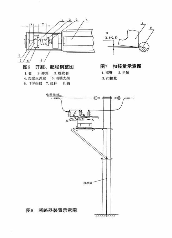
Four, storage and transportation and installation (see Figure 8)
1, the circuit breaker in the transport process, not flip, tilt, and the measures to prevent vibration, lifting the circuit breaker, must be hooked on the box 4 earrings, level lift, not 2 rings hanging hook on the box cover.
2, must be installed prior to the following monitoring
A, check whether the casing damage, divided, with instructions and storage indicates whether there are stuck, leakage and so on, the box has the phenomenon of deformation.
Isolation switch B, check the assembled rotation is flexible, on whether to place, opening is divided in place.
C, on a circuit breaker (including isolation switch) relatively, relative phase and voltage withstand test of 42kv/1min interrupter fracture by 80%. Such as when the isolation switch has the function of lightning protection, power frequency withstand voltage test must take isolation switch open.
3, when installing the circuit breaker, the staff shall not stand on the blade and contact isolation switch side, prevent breaking, foot slanting insulating shield and blade, contact isolation switch.
4, the circuit breaker mounting height should be according to the need of operation and maintenance, distance from the ground as far as possible, more than 2.8 meters.
In 5, the circuit breaker operation, both single rod installation, or double rod installation, do not have obvious shaking phenomenon.
6, the circuit breaker shall be reliably grounded.
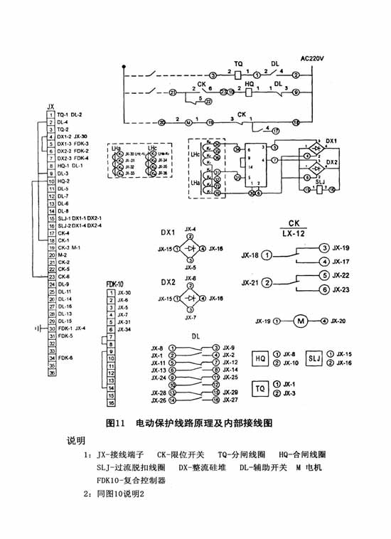
7, the circuit breaker control system schematic and wiring diagram shown in Figure 10, figure 11.
Five, the use method and the matters needing attention:
1, the circuit breaker body manual energy storage, 2~3 times of manual operation manual switch, manual switch, switch off state in the circuit breaker, isolating switch to manual switch, manual closing operation 2 ~ 3 times, observe its action is normal, mechanical interlocking structure between the circuit breaker body and with the isolation switch is flexible, reliable.
2, the circuit breaker is in before operation, must according to the actual situation of the transformation ratio current transformer are transferred to the appropriate location.
3, the circuit breaker every three years maintenance time, maintenance should be dust wipe the exposed parts and filth, and lubrication in all sports link graph fat.
Six, the common breakdown and processing
1, connect the power motor does not turn: check whether the motor power, power line is broken, the wiring is correct, the normal, the motor has a problem.
2, the motor can not be storage: check whether the two pawl pawl coordination, torsion of the spring is enough, if the energy storage spring has the energy storage, and energy storage pointer does not switch, that is mechanism cover installation error, should be re installed.
3, energy storage after the not gate: check the crank arm and half shaft buckle quantity and amount of clearance is in accordance with the requirements of Figure 7
Seven, random file and ordering instructions
1, random file
A, qualified certificate
B, installation instructions for use of the
A C, packing list
2, ordering instructions
A, to indicate the product name, model, specification, quantity, delivery time etc..
B, shall provide the user requirements, such as those functions, what mode of operation, the numerical ratio of current transformer, used in what kind of situation, tripping the fixed time.
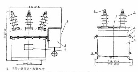
Fig. 1 the shape and size of the circuit breaker
The 1 rings of 2 porcelain sleeve 3 box cover 4 seal 5 lifting Earrings 6 box 7 conductive rod 8 switching indication 9 actuator 10 nameplate 11 air filtration device
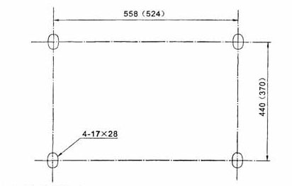
Fig. 2 mounting dimensions
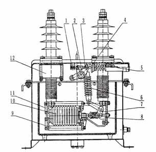
Fig. 3 the circuit breaker body structure
The 1 brake buffer 2 three-phase main shaft crank arm bracket 5 3 4 opening spring 6 insulating rod 7.7 words crank arm 8 end bracket 9 insulating rod 10 vacuum interrupters 11 static end bracket 12 current transformer
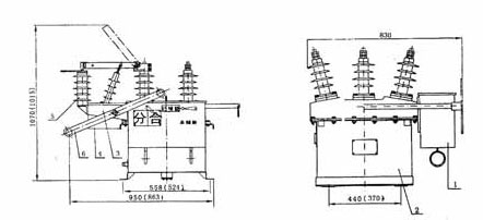
Figure 4 with isolation switch size
1 CT23 2 circuit breaker body 3 isolation switch 4 motor structure 5 support insulator (with a lightning arrester) 6 switch handle
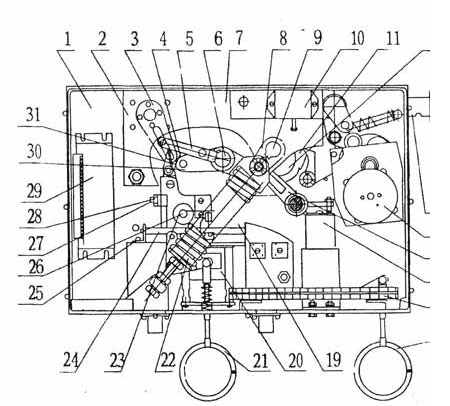
Figure 5a-CT23-D spring operating mechanism
The 1 floor 2 auxiliary switch 3 crank arm 4 5 6 7 drive shaft screw spindle support plate 8 energy storage crutch 9 energy storage shaft 10 stroke switch 11 ratchet 12 cam 13 energy storage handle 14 energy storage motor 15 positioning pieces 16 closing release 17 terminal 18 manual closing ring 19 interlocking device 20 tripping tripping 21 manual switching ring 22 closing spring 23 bent plate 24 release 25 adjusting screws 26 half shaft adjusting screw adjustment screw 27 28 29 30 31 roller rocker arm load controller
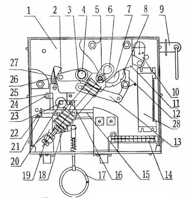
The 1 floor 2.. 3 screw spindle drive shaft 4 5 energy storage crutch 6 energy storage shaft 7 cam ratchet wheel energy storage handle 8 9 10 11 12 crank arm support plate to maintain a 13 win 14 terminal 15 tripping shaft 16 push rod 17 manual closing ring 18 closing spring 19 overcurrent release 20 axle 21 support plate 22 plate bending 23 adjusting screws 24 adjusting screws 25 arm 26 roller 27 composite controller
